Position the grid using markers
Check the apk version of your scanphone. > = 2.5 Alpha
Download and print the pdf document.
Cut out the 2 markers A and B. (6cm x 6cm).
Position Marker A at the top left and B at the bottom right.
When positioning the grid, visualize the Marker-A for a few moments, and a red circle will appear (this may take a few seconds). The grid configuration switches to parallel mode.
Then visualize the Marker-B. The application will draw a line between the 2 and position the grid in the center. You will be in parallel mode and you can set the height of the grid relative to the plane.

~ ~ ~ ~ ~ ~ ~ ~
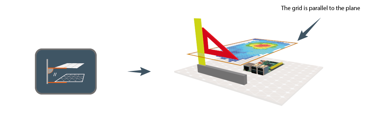
Orientation of the grid relative to the reference plane
– Mode parallel to the plan ( // ).
Adjustable Grid height, Automatic parallel
————————————————– Video demonstration ————————————————–
~ ~ ~ ~ ~ ~ ~ ~
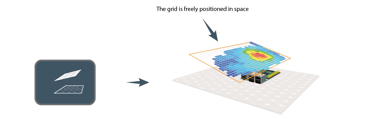
– Manual Mode
Grid is positioned anywhere in space
————————————————– Video demonstration ————————————————–
~ ~ ~ ~ ~ ~ ~ ~
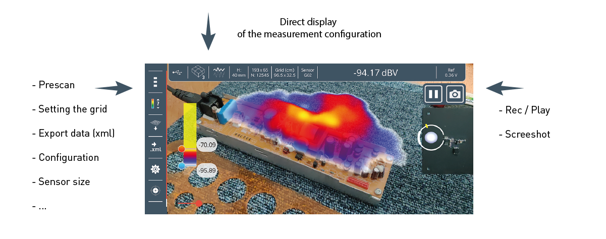
Main windows / Menu
- New application window
- Display parameter of the measurement
- Real-time modification of thresholds
- …
dBV to mA /m conversion for G02 sensor
– If the measured frequency is known